
C&I Storage Engineering · Published: 2026-09-18 · Updated: 2026-09-22 · 12 min read

Complete Engineering Guide to 16kWh~256kWh C&I Battery Sizing for Solar EPCs

Learn how to calculate peak shaving load requirements, select C-rates, design DC busbars, and configure 16kWh to 256kWh modular battery racks to eliminate commercial maximum demand charges.

SEL
Summit Engineering Lab Verified Engineering Lead
Technical Application & Power Systems Engineering Department
Chapter 01

1. Understanding Commercial Demand Tariffs & Peak Shaving Dynamics

In commercial and industrial (C&I) facilities, electricity utility bills consist of two distinct billing mechanisms: volumetric consumption charges (kWh) and maximum peak demand charges (kW or kVA). Across key markets in North America, Europe, Australia, and South Africa, peak demand charges frequently account for 35% to 50% of an enterprise's monthly power bill.

Unlike residential tariffs where consumers are billed solely on the total kilowatt-hours consumed over a month, commercial utility meters continuously record instantaneous average power in rolling 15-minute or 30-minute intervals. The single highest interval window recorded during on-peak operating hours dictates the demand charge tariff applied across the entire billing cycle.

The 15-Minute Peak Demand Trap

A sudden 100 kW load spike lasting only 20 minutes (e.g. cold-store compressor startup, metal stamping stroke, or multiple EV vans charging simultaneously) establishes the billing benchmark for all 720 hours of the month, incurring thousands of dollars in avoidable capacity penalty fees.
Chapter 02

2. The 3 Essential Sizing Formulas for Battery & PCS Sizing

To accurately size a commercial battery energy storage system (BESS), solar EPCs must balance discharge power (kW) to clip the peak spike against usable energy (kWh) required to sustain the discharge over the entire peak window.

Formula 01 · Peak Shaving Power Determines PCS / Inverter AC Rating
Pshave = Ppeak - Ptarget
P_peak (kW) Maximum recorded interval load demand from 15-min utility data.
P_target (kW) Target grid contract threshold ceiling to avoid penalty charges.
Formula 02 · Usable Battery Capacity Accounts for Efficiency & DoD
Eusable =
Pshave × tduration ηRTE × DoD
t_duration (Hours) Continuous duration load exceeds P_target (typically 1.5 to 3.0 hrs).
η_RTE (~90%) AC-to-AC round-trip system efficiency including inverter & BMS conversion.
DoD (~80%) Depth of discharge setting to preserve ≥6,000 cycle cell longevity.
Formula 03 · Nominal Installed Capacity Safeguards 10~15 Year Service Life
Enominal =
Eusable 0.80

Engineering Rule of Thumb: Always design with a 20% capacity buffer to guarantee contract performance commitments even after 10 years of operational cell degradation.

Interactive C&I Storage Sizing Calculator

Estimate required LPF-314AH battery cabinets and PCS inverter sizing in real time

LIVE SIMULATOR
Quick Presets:
200 kW
kW
120 kW
kW
2.0 Hrs
Hrs
Required Shave
80 kW
Continuous Peak
Usable Energy
222.2 kWh
90% RTE / 80% DoD
Summit LPF-314AH
14 Units
51.2V Rack Modules
Installed Capacity
225.1 kWh
Includes 20% Buffer
Recommended PCS: 100kW ~ 125kW Hybrid PCS
DC Bus Architecture: 14 cabinets parallel to common 51.2V DC busbar with CAN 2.0B bus.
Chapter 03

3. Real-World Engineering Case Study: 200kW Injection Molding Factory

To illustrate the mathematical principles in action, examine a manufacturing plant located in Poznań, Poland operating 6 hydraulic injection molding machines.

Baseline Factory Operational Profile

NO STORAGE
  • Continuous Base Load: 90 kW
  • Unmanaged Peak Spike: 195 kW (1.5 hrs)
  • Utility Demand Tariff: $16.50 / kW / mo
  • Annual Demand Charge: $38,610.00 / yr

Summit BESS Retrofit Solution

SUMMIT 128kWh
  • Installed Storage: 8x LPF-314AH (128.64 kWh)
  • PCS Capacity: 1x 100 kW Hybrid PCS
  • Target Grid Threshold: Capped at 115 kW
  • Peak Power Shaved: -80 kW Continuously
Demand Reduced -41.0%
Monthly Savings $1,320 / mo
Annual Savings $15,840 / yr
Simple Payback 2.42 Years
Financial Metric Before Storage After Summit 128kWh BESS Net Financial Impact
Billed Maximum Demand 195.0 kW 115.0 kW -80.0 kW (-41%)
Monthly Demand Charge $3,217.50 $1,897.50 Save $1,320.00 / mo
Annual Demand Savings $38,610.00 $22,770.00 Save $15,840.00 / yr
Total Simple Payback — — 2.42 Years Payback
Chapter 04

4. Modular 16kWh vs Monolithic 100kWh+ Architecture

When specifying commercial energy storage, engineering teams typically evaluate two competing architectural philosophies: heavy monolithic outdoor shipping containers (100kWh~500kWh) versus modular building-block battery cabinets (16kWh per unit).

01. Zero Crane Required

Standard Freight & Elevator Access

Monolithic containers require mobile cranes and civil concrete pads. Summit’s 16kWh LPF-314AH cabinet rolls smoothly through standard 900mm doorways and into commercial elevators on heavy-duty casters.

02. True N+1 Redundancy

Isolated Cell-Pack Servicing

If a single cell fault occurs in a monolithic container, the entire 100kWh system trips offline. In a 16-rack Summit system, one cabinet can be isolated while the remaining 15 units (240kWh) operate uninterrupted.

03. Linear Financial Scalability

CAPEX Phasing for Growing Loads

Enterprises rarely know their exact load 5 years out. EPCs can deploy 32kWh (2 racks) today, and seamlessly daisy-chain up to 16 units (256kWh) on the same DC busbar without replacing the hybrid inverter.

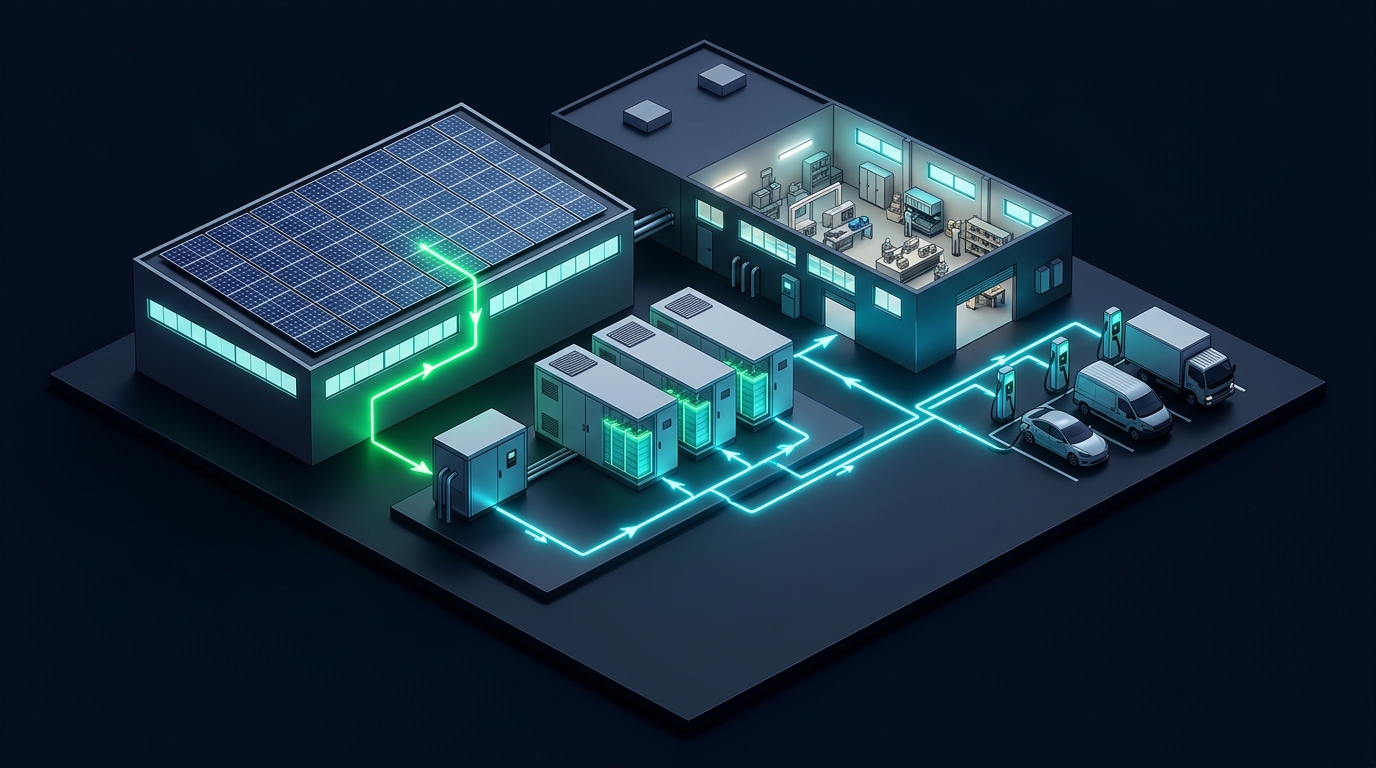
Summit C&I Energy Storage System Architecture Diagram
Figure 1: Integrated C&I Architecture combining rooftop solar, Summit LiFePO4 racks, PCS inverter, and commercial load.
Chapter 05

5. Sizing Matrix: 16kWh to 256kWh Reference Configuration Table

Use this standard engineering sizing matrix to pair facility square-footage and transformer ratings with the optimal number of LPF-314AH cabinets and hybrid PCS power ratings.

Storage Capacity Cabinet Qty Recommended PCS Target Facility Type Shave Capacity Est. Payback
16.08 kWh 1x LPF-314AH 8 kW ~ 15 kW Small clinic, retail store, estate mansion 10 kW max shave 3.2 ~ 3.8 yrs
32.16 kWh 2x LPF-314AH 15 kW ~ 25 kW Auto repair workshop, gas station, bakery 20 kW max shave 2.8 ~ 3.5 yrs
64.32 kWh 4x LPF-314AH 30 kW ~ 50 kW Small manufacturing, cold chain storage 40 kW max shave 2.5 ~ 3.2 yrs
128.64 kWh POPULAR 8x LPF-314AH 60 kW ~ 100 kW Industrial CNC plant, EV fleet depot 80 kW max shave 2.2 ~ 2.9 yrs
256.00 kWh 16x LPF-314AH (Max) 125 kW ~ 200 kW Industrial microgrid, logistics center 150 kW max shave 2.0 ~ 2.6 yrs
Chapter 06

6. DC Busbar Sizing, Protection & 16-Rack Parallel Wiring

When parallelizing multiple 51.2V battery cabinets, ensuring symmetric current distribution and adequate short-circuit protection is critical to electrical safety.

Busbar Copper Sizing (T2 Pure Copper):

  • 1 to 4 Racks (64kWh): 40mm × 5mm (400A continuous)
  • 5 to 8 Racks (128kWh): 50mm × 8mm (800A continuous)
  • 9 to 16 Racks (256kWh): 60mm × 10mm (1250A continuous)

Busbars must be plated with silver or nickel to prevent galvanic oxidation in high-humidity ambient environments.

Protection & Fusing Coordination:

  • Cabinet-Level: 250A MCCB 2-Pole per rack
  • Main DC Bus: 1250A Fast-Acting DC Fuse (gPV)
  • Interrupt Rating: 50 kA / 1 sec interrupt
  • Surge Protection: Type 1+2 DC SPD (1000V DC)

Each rack must utilize equal-length DC power cables to guarantee identical impedance and balanced cell aging.

Chapter 07

7. Inverter Protocol Handshake & DIP Addressing

Seamless closed-loop communication between the master BMS and hybrid inverter eliminates battery over-voltage trips and optimizes charging current limits automatically based on real-time cell telemetry.

Dual-Bus Protocol

CAN 2.0B + RS485

Simultaneous inverter handshake via CAN (500 kbps) and local EMS/SCADA monitoring via RS485 Modbus RTU.

Signal Isolation

2.5 kV Galvanic Isolation

High-voltage digital optocouplers prevent ground loops and inverter common-mode switching noise.

Bus Impedance

120Ω Built-in Resistor

Integrated terminal resistor prevents signal reflection over extended daisy-chain runs across up to 16 cabinets.

DIP SWITCH (4-BIT) MULTI-RACK ADDRESSING BAUD: 500 kbps (CAN) / 9600 bps (RS485)

When daisy-chaining multiple racks, configure Rack 1 as Master (DIP: 1-0-0-0). Subsequent units are addressed as Slaves from 0-1-0-0 (Node 2) up to 1-1-1-1 (Node 16). The Master BMS automatically polls all nodes and transmits aggregated SoC, voltage, and max charge/discharge current limits to the hybrid inverter via CAN bus.

Pre-Tested Inverters: Deye Growatt Victron Energy Solis GoodWe SMA

Need Engineering Assistance for an Upcoming Project?

Send us your 15-minute interval load data or electrical single-line diagram. Our senior application engineers will return a complete battery sizing report, SLD CAD drawing, and wholesale quotation within 12 hours.

Explore 16kWh Cabinet